|
Nanoscale materials have feature size
less than 100 nm – utilized in nanoscale structures, devices and systems
Nanoparticles and Structures
|
|---|
Nanoscale Materials


Nanotechnology Health and Environmental Concerns

− Human
and the environment come under exposure to nanomaterials at different stages of
the product cycle
− Nanomaterials
have large surface to volume ratio and novel physical as well as chemical
properties which may cause them to pose hazards to humans and the environment
− Health
and the environmental impacts associated with the exposure to many of the
engineered nanomaterials are still uncertain
− The
environmental fate and associated risk of waste nanomaterials should be
assessed – e.g. toxic transformation, and interactions with organic and
inorganic materials
|
|---|
Nanotechnology Applications

Information Technology
• Smaller,
faster, more energy efficient and powerful computing and other IT-based systems

Medicine
• Realization
of miniaturized devices and systems while providing more functionality
• Cancer
treatment
• Bone
treatment
• Drug
delivery
• Appetite
control
• Drug
development
• Medical
tools
• Diagnostic
tests
• Imaging

Energy
• More
efficient and cost effective technologies for energy production
− Solar cells
− Fuel cells
− Batteries
− Bio fuels

Consumer Goods
• Foods
and beverages
− Advanced
packaging materials, sensors, and lab-on-chips for food quality testing
• Appliances
and textiles
− Stain
proof, water proof and wrinkle free textiles
• Household
and cosmetics
− Self-cleaning and scratch free products,
paints, and better cosmetics
|
|---|
Nanoscale Size Effect
|
• Realization
of miniaturized devices and systems while providing more functionality
• Attainment
of high surface area to volume ratio
• Manifestation
of novel phenomena and properties, including changes in:
- Physical Properties
(e.g. melting point)
- Chemical Properties
(e.g. reactivity)
- Electrical
Properties (e.g. conductivity)
- Mechanical
Properties (e.g. strength)
- Optical Properties
(e.g. light emission
|
|---|
History of Nanotechnology

• 2000
Years Ago – Sulfide nanocrystals used by Greeks and Romans to dye hair
• 1000
Years Ago (Middle Ages) – Gold nanoparticles of different sizes used to
produce different colors in stained glass windows
• 1974 – “Nanotechnology” - Taniguchi uses the term nanotechnology for the first time
• 1981 – IBM develops Scanning Tunneling Microscope
• 1985
– “Buckyball” - Scientists at Rice University and University of Sussex discover
C60
• 1986
– “Engines of Creation” - First book on
nanotechnology by K. Eric Drexler. Atomic Force Microscope invented
by Binnig, Quate and Gerbe
• 1989 – IBM logo made with individual atoms
• 1991 – Carbon nanotube discovered by S. Iijima
• 1999
– “Nanomedicine” – 1st nanomedicine
book by R. Freitas
• 2000 – “National Nanotechnology Initiative” launched
|
|---|
What is Nanotechnology
| Header 1 |  
Nanotechnology is the creation of functional materials,
devices and systems, through the understanding and control of matter at
dimensions in the nanometer scale length (1-100 nm), where new functionalities
and properties of matter are observed
and harnessed for a broad range of applications
|
|---|
OSI REFERENCE MODEL
|
Introduction Advantages Networking Goals Networking Criteria Applications Common Terminology Used In Internet Network Topologies Types of Network LOCAL AREA NETWORK LAN Transmission Methods LAN Topologies LAN Devices Networking Basics OSI REFERENCE MODEL |
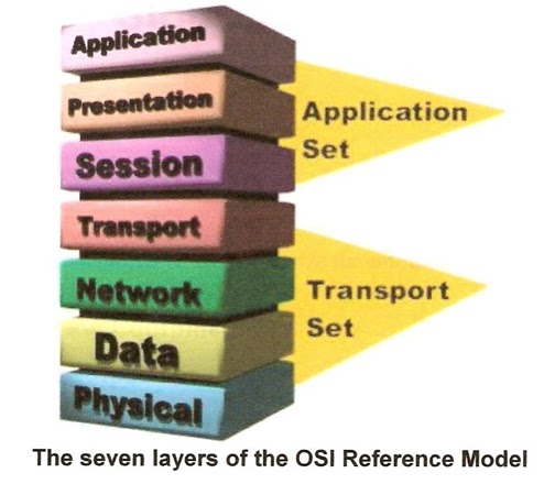
The Layers:-
Think of the seven layers as the assembly line in the
computer. At each layer, certain things happen to the data prepare it for the
next layer. The seven layers, which separate into two sets, are:
Application
Set
Layer 7:
Application- This is the layer that actually interacts with the operating
system or application whenever the user chooses to transfer files, read
messages or perform other network-related activities.
Layer 6: Presentation- Layer 6 takes the data provided by the Application
layer and converts it into a standard format that the other layers can
understand.
Layer 5:
Session- Layer 5 establishes,
maintains and ends communication with the receiving device.
Transport
Set
Layer 4:
Transport- This layer maintains flow
control of data and provides for error checking and recovery of data between
the devices. Flow control means that the Transport layer looks to see if data
is coming from more than one application and integrates each application’s data
into a single stream for the physical network.
Layer 3:
Network- The way that the data will
be sent to the recipient device is determined in this layer. Logical protocols,
routing and addressing are handled here.
Layer 2:
Data- In this layer, the appropriate
physical protocol is assigned to the data. Also, the type of network and the
packet sequencing is defined.
Layer 1: Physical- This is level of the actual hardware. It defines the
physical characteristics of the network such as connections, voltage levels and
timing.
 |
|---|
NETWORKING BASICS
|
Introduction Advantages Networking Goals Networking Criteria Applications Common Terminology Used In Internet Network Topologies Types of Network LOCAL AREA NETWORK LAN Transmission Methods LAN Topologies LAN Devices Networking Basics OSI REFERENCE MODEL |
Here are some of the fundamental parts of a network:
Network: A network is a group of computers connected together
in a way that allows information to be exchanged between the computers.
Node: A node is anything that is connected to the network.
While a node is typically a computer, it can also be something like a printer
or CD-ROM tower.
Segment: A segment is any portion of a network that is
separated, by a switch, bridge or router, from other parts of the network.
Backbone: The backbone is the main cabling of a network that
all of the segments connect to. Typically, the backbone is capable of carrying
more information than the individual segments. For example, each segment may
have a transfer rate of 10 Mbps (megabits per second), while the backbone may
operate at 100 Mbps.

Topology: Topology is the way that each node is physically
connected to the network (more on this in the next section).
Local
Area Network (LAN): A LAN is a
network of computers that are in the same general physical location, usually
within a building or a campus. If the computers are far apart (such as across
town or in different cities), than a Wide Area Network (WAN) is typically used.
Network
Interface Card (NIC): Every computer
(and most other devices) is connected to a network through an NIC. In most
desktop computers, this is an Ethernet card (normally 10 or 100 Mbps) that is
plugged into a slot on the computer’s motherboard.
Media
Access Control (MAC) Address: This is
the physical address of any device such as the NIC in a computer on the
network. The MAC address, which is made up of two equal parts, is 6 bytes long.
The first 3 bytes identify the company that made the NIC. The second 3 bytes
are the serial number of the NIC itself.
|
|---|
LAN Devices
|
Introduction Advantages Networking Goals Networking Criteria Applications Common Terminology Used In Internet Network Topologies Types of Network LOCAL AREA NETWORK LAN Transmission Methods LAN Topologies LAN Devices Networking Basics OSI REFERENCE MODEL |
Devices commonly used in LANs include repeaters, hubs,
LAN extenders, bridges, LAN switches, and routers.
A Repeater us a physical
layer device used to interconnect the media segments of an extended network. A
repeater essentially enables a series of cable segments to be treated as a
single cable. Repeaters receive signals from one network segment and amplify,
retime, and retransmit those signals to another network segment. These actions
prevent signal deterioration caused by long cable lengths and large numbers of
connected devices. Repeaters are incapable of performing complex filtering and
other traffic processing. In addition, all electrical signals, including
electrical disturbances and other errors, are repeated and amplified. The total
number of repeaters and network segments that can be connected is limited due
to timing and other issues. Figure illustrates a repeater connecting two
network segments.
Figure: A Repeater Connects Two Networks Segments
 
Switches are another
fundamental part of many networks because they speed things up. Switches allow
different nodes (a network connection point, typically a computer) of a network
to communicate directly with one another in a smooth and efficient manner.
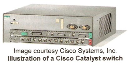
There are many different types of switches and
networks. Switches that provide a separate connection for each node in a
company’s internal network are called LAN switches. Essentially, a LAN switch
creates a series of instant networks that contain only the two devices
communicating with each other at that particular moment.
|
|---|
LAN Topologies
|
Introduction Advantages Networking Goals Networking Criteria Applications Common Terminology Used In Internet Network Topologies Types of Network LOCAL AREA NETWORK LAN Transmission Methods LAN Topologies LAN Devices Networking Basics OSI REFERENCE MODEL |
LAN topologies define the manner in which network
devices are organized. Fore common LAN topologies exist: Bus, Ring, Star, and
Tree. These topologies are logical architectures, but the actual devices need
not be physically organized in these configurations. Logical bus and Ring topologies, for example, are commonly
organized physically as a Star.
A Bus topology is a linear LAN
architecture in which transmission from network stations propagate the length
of the medium and are received by all other stations. Of the three most widely
used LAN implementations, Ethernet/IEEE 802.3 networks-including 100 Base
T-implement a bus topology, which is illustrated in Figure.

A Ring Topology is a LAN
architecture that consists of a series of devices connected to one another by
unidirectional transmission links to form a single closed loop. Booth Token
Ring/IEEE 802.5 and FDDI (Fiber Distributed Data Interface) networks implement
a ring topology. Figure depicts a logical ring topology.
Figure: Some networks Implement a Logical Ring Topology

A Star Topology is a LAN architecture in which the endpoints on a
network are connected to a common central hub, or switch, by dedicated links.
Logical bus and ring topologies are often implemented physically in a star
topology.
A Tree Topology is a LAN architecture that is identical to the bus
topology, except that branches with multiple nodes are possible in this case.
Figure illustrates a logical tree topology.
Figure: A Logical Tree Topology Can Contain Multiple Nodes
 |
|---|
Subscribe to:
Comments (Atom)